Further programming the Arduino robot
| Aim | Introduce textual programming to the students by means of the resolution of simple problems related to concepts linked with the operation of sensors and actuators of the robot: blinking control leds, moving the robot (straight line, turnings), reactions to collisions, following lines, sending messages to LCD to help debugging, etc. |
|---|---|
| Duration | 2.5 - 3 hours |
| Technology | One PC/laptop per robot/arduino board. It is a offline activity, but the most appropriate version of Arduino IDE software must be downloaded from the Arduino web site if it is not already installed on the computers (https://www.arduino.cc/en/Main/Software); Mobile Robot (Arduino UNO-based robot); USB programming cable; Spare bateries. |
| Student/teacher Ratio | 8:1 |
| Age of students | 12 – 14, but the activity can be adapted for more advanced students introducing other concepts. |
Special Requirements
The teacher will require a basic knowledge of electronics (basics about sensors, actuators and schematics), programming (principly with Arduino-based systems), and PC configuration (to establishing USB connections, installing drivers, etc). The "help” menu in the Sketch window of the Arduino IDE software can provide useful information.
Students will require very basic knowledge of basic electronics (LEDs, DC motors, encoders, optical sensors), and also some knowledge about programming basics.
It is necessary to have a completely assembled and tested robot for this activity and space in the classroom to operate it.
Project Overview
Students will build small pieces of program that control different elements of the robot. They should have or acquire a knowledge of the structure of a program, including libraries and definitions and how to use the IDE for coding and testing. Initialization of actuators (motors and LEDs) and sensors (bumpers, encoders, optical sensors, etc.) and how to read inputs and write to outputs will be covered: First will be digital output to the LEDs and then this will be extended to analog output to control motors to move the robot a specific distance. Then, it is interesting to introduce mathematical concepts related to odometry and encoders. It would be nice to introduce the basics about LCD programming to be able to send messages to that device.
Steps to follow to carry out the activity
- Figure 1 shows the Arduino IDE programming interface. It is possible to Write a new program, verify and stop a program, Open and Save a file, open the Serial Console, Load the program onto the board, etc.
In the option “Tools > Port” it is possible to select the proper communications port used to connect our computer with the Arduino board. Students should be made familiar with this procedure to ensure connectivity.
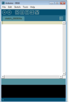
Figure 1 The Arduino IDE Programming Interface.
- Analyze the structure of an Arduino program (Includes, Definitions, Initializations, Code, Setup and Loop functions). Figure 2 shows the basic outline of an Arduino program (in C).
//#define red 8 (definitions)
//int timer = 1000; (variables and initializations)

void setup() {
  // put your setup code here, to run once:
}

void loop() {
  // put your main code here, to run repeatedly:
}
Figure 2 Outline of an Arduino program
- Build or rewrite a very simple TEST program and upload it to the Arduino board of the robot: Testing the program.
Time required to write, to check for errors, to upload to the board is approx. 10 minutes
Here a very simple TEST example: “blinking red led one second”
define red 8 //you can see in schematics of the board that red led is connected to digital output 8 when it is used //an Ardubot Robot
int timer =1000; // timer = 1000 means 1 second aprox.
void setup() { pinMode(red,OUTPUT); }
Void loop() { digitalWrite(red,HIGH); delay(timer); digitalWrite(red,LOW); delay(timer); }
Students can now make changes in the different lines of the code and analyze what are the new results. Creation of a "traffic light" simulation is a good objective. The students have to know where the green and yellow leds are connected (pins 6 and 7 respectively using Ardubot Robot).
4.-Operation of the robot when hitting an obstacle (using switches placed in front of the robot)
This is another very simple example related to reading the state of a switch (input). In the case of the Ardubot robot the red led located at the output 8 will follow the state of that specific input (switch connected to pin 13).
Time approx. 30 minutes (including changes and different kind of trials)
unsigned char switchstate
void setup() { pinMode (13,INPUT); pinMode (8,OUTPUT); }
void loop() { switchstate=digitalRead(13); if (switchstate==HIGH) { digitalWrite(8,HIGH); } else { digitalWrite(8,LOW); } }
Here an if-else programming structure is introduced.
5.-Start moving the robot: specific distances and turnings (first using time and then working with encoders and odometry concepts. Setting up PWM for the two motors-wheels)
You have to look at the documentation to analyze how to deal with PWM signals to be sent to the motors to control the speed, and how to read the signals coming from the encoders to compute the distance covered by the robot and the turning ratio.
First, the students should discover how to use the analogWrite instruction with the proper pins. If you look at the Ardubot specific documentation you will discover that the DC motors attached to right and left wheels are connected to the pins 10 and 5 and the pins 9 and 11, through a power driver (L293).
If you want to turn one of the motors in one direction with a specific speed, you have to program:
analogWrite(10,100); analogWrite(5,0);
If you want to turn that motor in the oposite direction with a different speed (a little bit higher), then you can do the following:
analogWrite(10,0); analogWrite(5,150);
As a pice of advice, in case of using Ardubot robot, it will be necessary to connect the batteries to correct places when you are doing experiments with the motors.
You can use libraries available for Arduino boards or also specific libraries built, as for instance Ardubot.h library. This library was designed to facilitate programming of different resources of the Ardubot robot (I/O pin configurations, I/O operations, PWM management, using encoders, etc.).
Time required to explain all the concepts related to PWM and speed of the motors, use of encoders and Ardubot library, checking the program, and trying to test different kind of proposals is approx. 75 minutes.
As a very simple example, imagine you want to move the robot forward at maximum speed. Then, we have:
include Ardubot.h void setup() { Ardubot.SETpinMode(); //proper configuration of all the I/O pins Ardubot.InitPWM(); // proper configuration of all the timers involved on the generation of PWM signals }
void loop() { Ardubot.SETpwm(100,100); // left and right motor to maximum speed forward // we can set the values between -100 (maximum speed reverse) and +100 (maximum speed forward) }
Tips to make the workshop go smoothly
Download the ARDUINO software (http://www.arduino.cc/en/Main/Software) and install it on the computer (technical help may be required to install the drivers and to check that they are OK). Approx. 30 minutes. You need to be familiar with the pins on the Arduino Board of the robot where the actuators and the sensors are connected. You also need to know the functions of the different libraries. Prepare a set of spare batteries. Prepare properly the workshop in advance. Teachers should try to do the workshop before conducting it with the students. Projector and blackboard are very useful tools to help to conduct the workshop.
Extensions and challenges
It is possible to propose more challenging projects using the robot, the Arduino Board and other external modules, sensors and actuators that can be connected easily. It is also possible to investigate the different available libraries and use them to create different projects.
Sources of additional information
www.arduino.cc
You can find Examples and Libraries in the options "files" and "Sketch" of the Arduino IDE programming interface.
Documentation and description of Ardubot Robot (mainly, schematics).
Documentation of library Ardubot.h